CHAPTER 5: BUILDING CODE ANALYSIS
- Katie Hepting
- Nov 23, 2024
- 8 min read

Updated: Dec 1, 2024
As of the time of this writing, the jurisdiction of the City of Saint Louis adheres to the following versions of code building and related codes:
2018 International Building Code (IBC)
2018 International Existing Building Code (IEBC)
2018 International Energy Conservation Code (IECC)
2018 International Fire Code (IFC)
2021 Uniform Plumbing Code (UPC)
2018 International Mechanical Code (IMC)
2018 International Fuel Gas Code (IFGC)
2017 National Electrical Code (NEC)
BUILDING CODE SUMMARY
Occupancy Classifications: A-2, A-3, B, M, S-2
Construction Type: 1B, Fully Sprinklered
Allowable Building Area: Unlimited
Allowable Building Height: 180’
Allowable Number of Stories Above Grade: 12
The IBC has several requirements for underground spaces to ensure safety and accessibility of a building’s users. Underground spaces should be Type I construction, and in this case no modifications are anticipated to be required as the underground cellars are constructed of masonry and concrete, which meet the materials requirements for this category. An automatic sprinkler system will be installed throughout the entirety of the cellars for added protection, along with a fire alarm system. A smoke control system will also be installed in order to direct smoke away from the means of egress in the event of an emergency. Each underground level will have two exit points that provide a clear path to safety outside, and stairwells will be smokeproof enclosures that act as areas of refuge. Emergency power will be provided so that communication systems, fire alarms and sprinkler systems, elevator car lighting, means of egress illumination, and fire pumps can remain functional in case of a power failure.
Table 601 from the International Building Code will be adhered to when choosing building materials. In addition, the fire resistance ratings of building elements, components, or assemblies shall be determined in accordance with test procedures set forth in ASTM E119 or UL 263, or in accordance with Section 703.3 of the IBC. Primary structural members that are intended to remain exposed will be coated with intumescent paint in order to comply with these requirements. Both new and existing walls will be fitted with weather protection such as flashing in order to ensure the building envelope is as air- and water-tight as possible.

The entire building will be fitted with an automatic sprinkler system and fire alarms throughout, and regular maintenance and monitoring will be performed. The sprinkler riser will be located on the northeast corner of the ground floor and shall be clearly marked so that it is easy to locate from the exterior and interior. The room will typically be locked, but a key will be available at all times in a Knox Box on the exterior of the building allowing the fire department to enter even outside of normal business hours.

Based on table 1004.5 in Chapter 10 of the IBC, the occupancy of the building has been determined to be 968.3, but will be rounded up to 969 persons. The image above demonstrates the breakdown of each occupancy type, detailed per floor, and notes the load factors used in calculations.
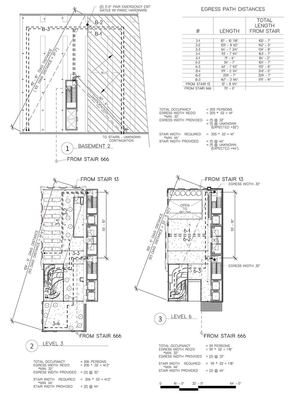
Due to the occupancy load of 969 persons, three exit access points are required and have been provided as shown below. Two exit points are provided at the ground level of the Malt Kiln, while the third will be accessed through the cellars. Additional exit doors are provided at the main entrance above and beyond the required number of exits.
Egress width required: 969 x .2 = 193.8”
Egress width provided: =(2) @ 32”
=(3) @ 68”
Total: =268”
In the entry area, three sets of double doors are provided with clear exit widths of 68”. Because these doors are in close proximity to each other and do not satisfy the IBC’s requirement of being located at least one third of the diagonal distance of the entire building apart to be counted as separate exit points, they are only counted as one. However, their clear opening widths can be combined to count as part of the total egress width requirement. As people are more likely to exit a building at the same point they entered from as it is familiar, it is considered good practice to provide a greater amount of egress at said entrance than other exits, above and beyond the code requirements.
Figure 66 demonstrates typical paths of egress in the building. It is anticipated that upgrades to the existing stairs at the far end of the cellars will need to be replaced in order to meet code and provide a safe path of travel, but further assessment is needed to understand the scope of work. Two stairwells are provided for emergency vertical egress and can function as areas of refuge as they are fully enclosed in concrete masonry unit block. As the cellars are constructed from stone and concrete and greatly separated from the building above, they could serve as areas of refuge themselves.
The entire building will be equipped with accessibility features, so that persons of all abilities may access any area of the building unassisted. Elevators are provided with access to every floor. Doors will be either automatic motion or button operated doors, or will be equipped with compliant door hardware and will have an opening force of less than five pounds. Restrooms will provide generous space to fit all required restroom element clearances. Doors will be installed so that they have required operating clearances, and in the case of recessed doors, modifications to existing walls will be made to meet the requirements for clearances at recessed doors.
Clear signage will be provided at all areas of the building where uses might not be immediately apparent, such as at restrooms. Signage will include contrasting lettering and backgrounds, and will have braille in the required location on the signage.
Once the occupancy load was calculated, the number of required plumbing fixtures were calculated based on table 2902.1 in Chapter 29 of the IBC, as shown below. The calculations for the minimum requirements will be rounded to the following numbers:
Total toilets: 12
Total lavatories: 6
Total Drinking Fountains: 2

The building is expected to be utilized equally by all genders, and intends to be inclusive to every person. The planned interior layout includes two accessible single-use toilet rooms on each floor, each including one toilet, one lavatory and typical accessories. A high-low drinking fountain will be provided on Level 1A to satisfy this requirement, but drinking water will be available from other sources on nearly every floor. Service sinks will be provided at the areas that would need to utilize them for janitorial services.
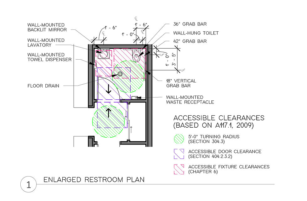
Typical accessible restroom layout
ENERGY CODE
According to the IECC, the City of St. Louis is located in climate zone 4A, denoting a humid yet typically moderate climate. Keeping the existing brick exposed on all sides is a cornerstone to this project, but in doing so it will not be fitted with continuous insulation as the IECC Prescriptive method requires. For this reason, the Prescriptive Method will only be followed for new elements, while the Performance Method of energy conservation will be utilized for the existing mass walls. This allows the thermal properties of all new and existing materials and systems to be compiled so that calculations can be carried out to demonstrate equivalent compliance with the code.
The existing mass brick walls will not be insulated in any way to most importantly to achieve the preservation of a historically significant and beloved building, but also to ensure that the porous brick and stone are allowed to breathe as they were built to do over one hundred years ago. As stated in the literature review, mass brick walls will absorb moisture, but they are quick to dry out when airflow is present on all sides of the wall. If insulation were to be installed even just on one side, this drying property is inhibited which can lead to cracking and deteriorating from freezing and thawing cycles, and also to mold and mildew growth.
To offset the thermal properties of the uninsulated brick walls, the building will be over-insulated in every area possible. The new additions will be constructed of “Hi-R” concrete masonry units, insulated metal studs, or a combination of both. Unfortunately, the existing windows do not appear to be in good condition. In order to preserve the historic character of the building, each window will be carefully assessed and will either be retrofitted with new double pane glass, or an exact replica will be produced also with double pane glass. This project will involve the addition of more windows in the existing brick where the façade pattern makes locations of possible future windows obvious, and at these locations the replicas produced will be tightly fitted and installed with weather- and air leakage-proof gaskets to minimize disruptions in continuity of the thermal envelope. The rear exterior door will be replaced with an insulated metal replica to further seal the building envelope. At the new entry points, new glass doors will be installed with good thermal resistance properties, which will be manually operable or operable with an actuator. Motion sensors will not be considered at these entry doors as they are bordering a neighborhood sidewalk and could be triggered by passers-by on accident many times per day.
The new portions of the building will follow the Prescriptive thermal envelope requirements listed in table C402.1.4 of the IECC. The following is a summary of requirements that will be met:
Mass Walls, above grade: Maximum U-Factor of U-0.104
Metal Framed Walls, above grade: Maximum U-Factor of U-0.064
Floors, Joist framed: Maximum U-Factor of U-0.033
Slab-on-grade Floor: Maximum F-Factor of F-0.54
New interior and exterior walls will be framed with metal studs, with a typical spacing of 16” on-center. Insulation in walls framed with 3 ½” metal studs shall have a minimum R-Value of 15, and in walls framed with 6” metal studs a minimum R-Value of 21. The new roof will exceed the required minimum R-Value of R-30 in order to balance the performance of the uninsulated brick walls. In addition to incorporating 4” thick standard extruded polystyrene insulation with an R-Value of R-20, an additional layer of 2” thick vacuum insulated panels with an added R-Value of 57 will be installed for a total R-Value of R-77. By over-insulating the roof to this degree, it is expected that heat will be retained in the winters to keep the interior very comfortable.

Typical detail showing roof construction with vacuum insulated panels
Additionally, to ensure minimal air leakage from the thermal envelope, weather-proof gaskets with thermal properties will be installed at all joints between new and old walls. Exhaust fans will be installed in the vertical garden walls leading to the interior and will be attached to thermostats so that excess heat trapped in the glass enclosure can be re-distributed in cold weather to reduce the load on the HVAC system. Finally, the heat transfer anticipated from the brewery equipment and the assembly occupancies can further lighten the load on the HVAC system in colder months.
It is expected that maintaining a comfortable interior temperature during winter will be easily achievable. In the summer the HVAC system will need to work a bit harder to offset some of the design features that might keep heat in. One of the main contributors to buildings overheating in the summer is the placement of windows on the south wall of the building. The Malt Kiln will have no windows on the south wall – instead, it will have insulated concrete masonry units beyond the existing brick wall shared by the neighboring brewery building. This design will eliminate one of the major causes of interior heat gain and is expected to allow the building to be comfortable during the summer months without issue.
With the design intent completed, the Revit model would be sent to an energy consultant to validate the initial calculations and provide further insight as to what additional modifications could be made to increase energy efficiency.


Comments